Over time corrosive soils with high moisture and salt content and high temperatures can degrade ground rods and their connections.
Ground mat resistance testing procedures.
Determining effectiveness of ground grids and connections that are used with electrical systems to protect personnel and equipment.
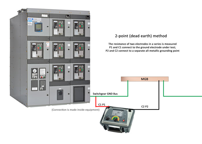
The shortcut test is made by simply connecting a piece of test equipment between the test electrode and a remote ground and then measuring a loop resistance.
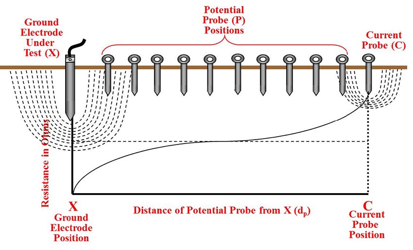
Ground mat resistance testing setup fall of potential method 1 to provide additional insulation to personnel during the test place an insulating platform or rubber blanket.
The method is easy but it loses accuracy because all the other elements in the loop are part of the measurement.
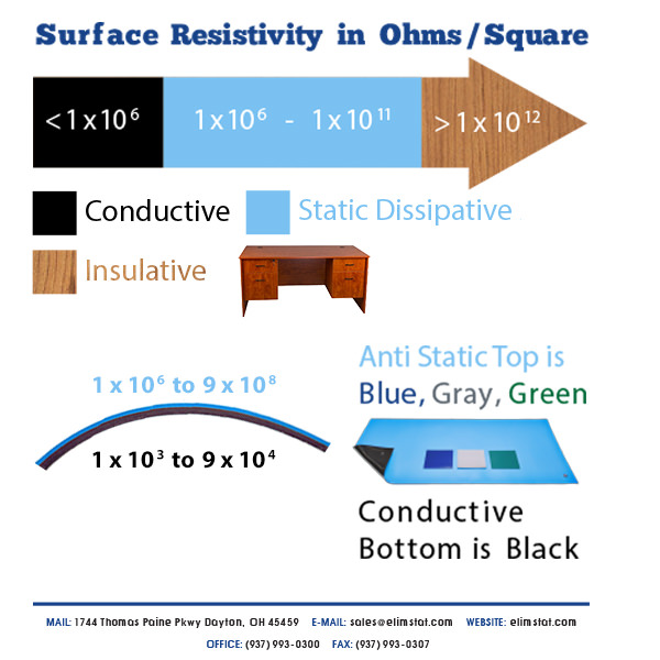
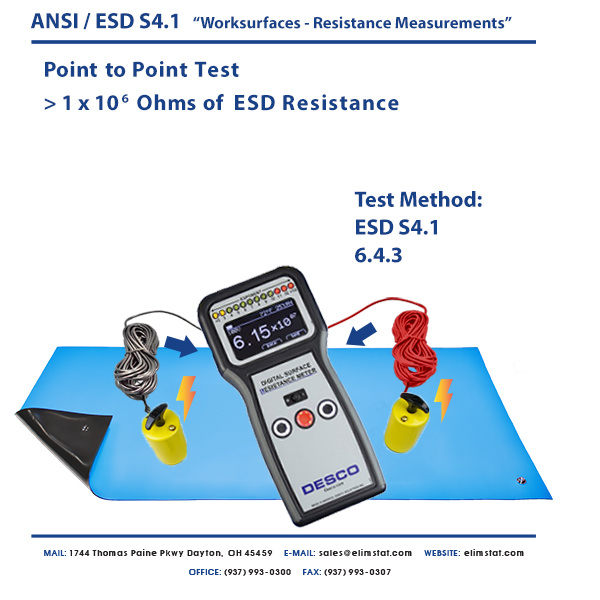
The standard used internationally to test anti static mats is esd association standard test method stm 4 1 2017 worksurfaces resistance measurements.
Dp distance between ground mat system and potential probe.
The most common methods of measuring the resistance of an earth electrode this method is derived from the 4 point method which is used for soil resistivity measurements.
It recommends two tests resistance measured top to top rtt and resistance measured top to ground rtg.
This method is not as accurate as three point methods as it is particularly affected by the distance between the tested electrode and the dead ground or water pipe.
This test uses a special transformer to induce an oscillating voltage often 1 7 khz into the grounding system.
The goal in ground resistance testing is to achieve the lowest ground resistance value possible.
Earth resistance is measured in two ways for two important fields of use.
Dp distance between ground mat system and current probe.
Ground resistance testing principle 2.
The induced frequency testing or commonly called the clamp on test is one of the newest test methods for measuring the resistance to ground of a grounding system or electrode.
2 point dead earth method in areas where driving ground rods may be impractical the two point method can be used.
This method should not be used as a standard procedure but rather as a back up in tight areas.
Four of the most common methods of ground resistance testing used by test technicians are discussed below.
Prospecting for good low resistance ground locations or obtaining.
Poor grounding contributes to downtime but a lack of good grounding is also dangerous and increases the risk of equipment failure.
The procedures for earth resistance testing are referenced in ieee standard no.


